

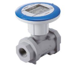
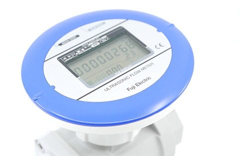
Ultrasonic flow meter for air - FWD-A
ref : FWD-AFrom
2298,00 € DiscoverThanks to its innovative technology, the compressed air flow meter can monitor air consumption, identify leaks and adjust compressor parameters to optimize energy efficiency.
This mass flow meter for compressed air marks a real technological breakthrough in air flow measurement. It allows to highlight your compressed air consumption. Its objective is to make important energy savings by identifying the consuming networks and the compressed air leaks. With a flawless accuracy, this mass flow meter allows you to control and adjust the parameters of your air compressor.

Efficient use of energy helps control costs and reduce the negative impact on the environment.
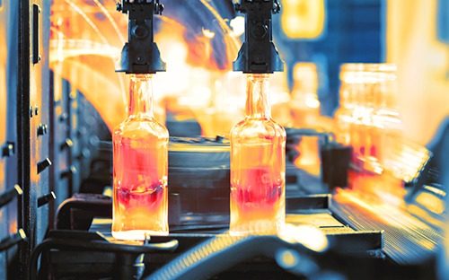
Among industrial utilities, compressed air represents up to 20% of the total energy budget of a factory.
The need for this gas is one of the largest electrical consumption items, but the price of this energy can be controlled.
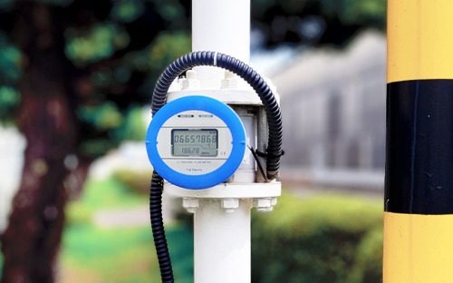
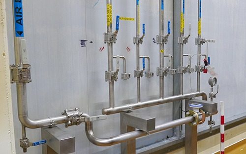
Flow meters are used in compressed air systems to provide a measure of flow rate through air velocity. Compressed air systems typically have high leakage rates, high start-up and shutdown times, and other problems that lead to losses and therefore waste. Industrial air flow meter can identify areas of excessive use and better manage the overall flow of the compressed air system.
Measuring, analyzing and communicating key plant performance indicators can then help educate personnel on efficient practices, thereby controlling costs, ensuring better equipment protection and saving money.

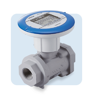
Fuji Electric flowmeters for compressed air consist of two ultrasonic sensors installed on either side of the meter inlet and outlet.
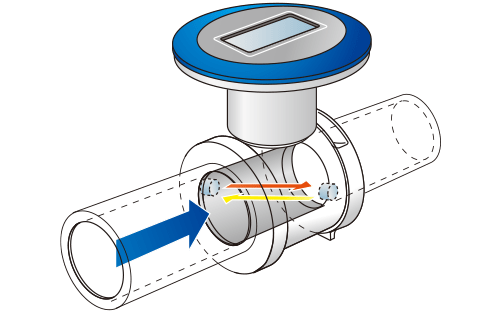
As the liquid flows, the ultrasonic waves propagate diagonally from the upstream sensor to the downstream sensor and back in the pipe where the mass flow meter is positioned.
With this technique, the waves are "carried" by the fluid, in the other, they are "braked".
It therefore takes a different time to pass from one sensor to the other. This difference is proportional to the velocity and therefore to the flow rate of the fluid.
This time difference allows to detect the fluid flow velocity and to calculate the volumetric flow rate according to the cross section of the flow meter and the Measuring principle - how to measure a compressed air flow rate FWD screenflow velocity measurement.
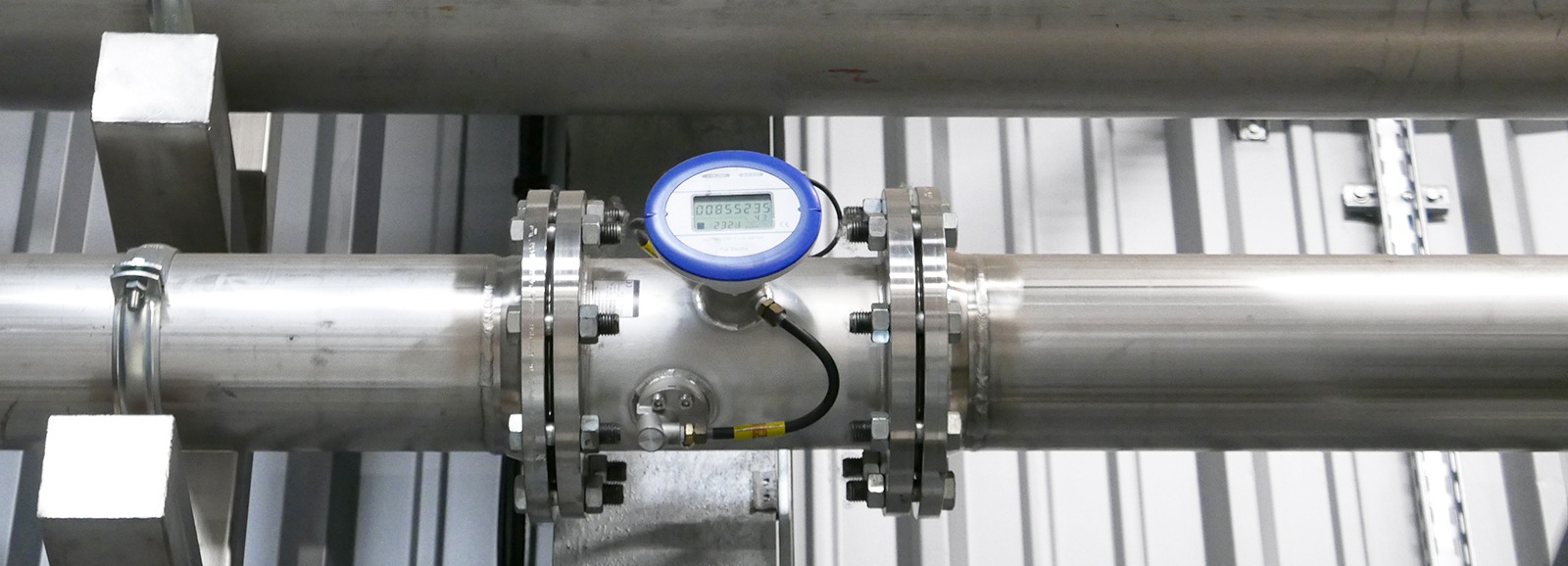
The number of measuring points of compressed air flow meters must be adapted to the size and use of the system. In contrast to thermal mass flow meters or vortex flow meters technologies, the FWD ultrasonic flow sensor technology does not clog and is highly resistant to oil-contaminated compressed air. It works even in the presence of water droplets (high dew point).
The combined measurement of flow rate, velocity, temperature and pressure, provides clear data on compressed air consumption and eliminates any uncertainty in the measurement.
These air flow sensors are resistant to industrial environments and vibrations.
These air flow devices are ideal for companies operating in an industrial environment.
As an instrumentation specialist, manufacturer of pressure transmitters and expert in gas analysis, our expertise extends to all industrial measurement solutions: pressure measurement, flow measurement, level measurement, temperature control, gas analysis and radiation monitoring.
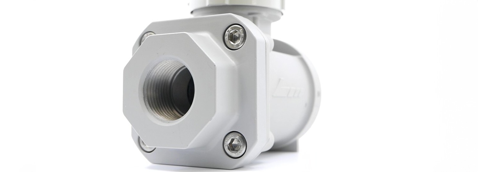
Screw-on models ∅25 and 32mm
Wafer models ∅40, 50, 65 and 80mm
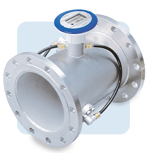
Flange models
∅100, 150, and 200mm
| Pipe diameter (mm) | DN25, DN32, DN40, DN50, DN65, DN80, DN100, DN150, DN200 | |||
| Supply voltage | 24 V DC ±10% or built-in battery type (battery life : approx.10 years at 20˚C) | |||
| Power consumption | 24 V DC, 1.5 W or less | |||
| Applicable fluids | Air (mainly factory air) or Nitrogen (25-80 mm diameter) | |||
| Fluid temperature | 10°C to 60°C, RH 90% or less | |||
| Working pressure | Less than 1 MPa (gauge pressure) | |||
| Range (actual flow rate) and accuracy | Diameter | Flow rate range (m 3/h) | Accuracy | |
| ±2.0% of flow rate | ±5.0% of flow rate | |||
| DN25 | ±0.6-35 | ±3.5-35m3/h | ±0.6-3.5m3/h | |
| DN32 | ±1.1-65 | ±6.5-65m3/h | ±1.1-6.5m3/h | |
| DN40 | ±1.3-80 | ±8-80m3/h | ±1.3-8m3/h | |
| DN50 | ±2.5-150 | ±15-150m3/h | ±2.5-15m3/h | |
| DN65 | ±4-240 | ±24-240m3/h | ±4-24m3/h | |
| DN80 | ±5-300 | ±30-300m3/h | ±5-30m3/h | |
| DN100 | ±10-500 | ±50-500m3/h | ±10-50m3/h | |
| DN150 | ±24-1200 | ±120-1200m3/h | ±24-120m3/h | |
| DN200 | ±40-2000 | ±200-2000m3/h | ±40-200m3/h | |
| Air flow rate conversion accuracy | FWD025-080: ±2.5% of reading (at 500 kPa, 25°C, dry air) FWD100-200: ±2.0% of reading (at ≥ 300 kPa) | |||
| Display | 1st line | Totalized value (m3) 8-digit, Instantaneous flow (l/mm) 8-digit | ||
| 2nd line | Instantaneous flow (Nm3/h) 5-digit (4-digit after 2000), Pressure (kPa) 5-digit, Temperature (°C) 3-digit | |||
| Output signal (not available for battery-driven version) | Current output | 4-20 mA DCC (±0.5% PE), max. load resistance. 400Ω, max. current output 22 mA Instantaneous flow, pressure, or temperature | ||
| Contact output | 2 contact outputs, max. load 24 V DC, 50 mA, max. frequency: 10 Hz,Output 1: pulses (forward), Output 2: pulses (reverse), high/low alarm, system error | |||
| Process connection type | ⌀25, ⌀32 mm | ⌀25 mm: Rc1, ⌀32 mm: Rc1-1/4 | ||
| ⌀40-⌀80 mm | Flange mounting (JIS10K) | |||
| ⌀100-⌀200 mm | Flange mounting JIS10K | |||
| Process connection type | ⌀25, ⌀32 mm | 20D or more upstream, 5D or more downstream When used for bidirectional measurement, 20D or more upstream and downstream | ||
| ⌀40-⌀200 mm | 10D or more upstream, 5D or more downstream When used for bidirectional measurement, 10D or more upstream and downstream | |||
| Materials of wetted parts | Aluminum alloy, PPS, fluorosilicone rubber, etc. | |||
| Installation location | Indoor or outdoor (IP64 equivalent) | |||
| Storage temperature | -20°C to 70°C, non-condensing | |||
Ultrasonic flow meter for air - FWD-A
ref : FWD-AFrom
2298,00 € Discover
Ultrasonic flow meter for gas nitrogen battery powered - FWD-N
ref : FWD-N - BATTERYFrom
2298,00 € Discover
Ultrasonic flow meter for air battery powered - FWD - A
ref : FWD-A - BATTERYFrom
2298,00 € Discover
Ultrasonic flow meter for gas nitrogen - FWD-N
ref : FWD-NFrom
2298,00 € Discover